The Eighties have seen proliferation of personal use recording studios tailored to the requirements of leading artists and record producers. It is important to understand some of the basic reasons for the increased popularity of home studios in the production of professional product:
- An abundance of used state of the art equipment at a reasonable price;
- A trend towards the use of more electronic musical instruments, and a related decline in the use of acoustic instrumentation;
- With overdubs consuming 50% or more of a product’s budget, it is cost effective for a project to be taken to a personal use studio (suitably equipped);
- User creativity is increased when projects can be done without studio time restrictions; and
- New digital reverb technology enables a variety of room sounds to be created, regardless of the actual studio size.
The home studio, with proper layout and execution, is able to handle an increased variety of projects, yet still capable of producing a quality product. While the creation of a quality personal use studio shares similar problems to a commercial facility construction techniques, isolation, room geometry, etc. unique problems are frequently encountered. (One of which is the studio’s ability to contain sound pressure levels in excess of 130 dB without disrupting adjacent neighbors.)
Personal Use Criteria
One of the first steps in pre-planning the facility is to list the requirements and clarify the goals the user expects from the studio:
- Is the facility to be used just for overdubs and mixing?
- Do keyboards represent a major usage of the studio? If so, does sufficient space need to be provided in the control room to accommodate them?
- Do they need a 24 track studio?
- Budgetary considerations; and
- Future expansion requirements.
One begins by finding a suitable location for the room. Size requirements and sound containment techniques will dictate construction practices. At this point, I can’t over emphasize the need to consult a competent architect and studio construction specialist familiar with all aspects of studio construction techniques.
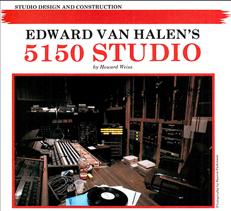
A good case in point was the construction of 5150 (Police code for “Mental Case”), the studio we built recently for Edward Van Halen, and the recording and mixing venue for his 1984 album. Design requirements for the studio were set down by Ed and his engineer, Donn Landee. Basically, Ed wanted a room where “we could make records;” a place he could use at any hour and not be concerned with disturbing anyone. Donn wanted “a semiprofessional 16/24 track studio to accommodate tracking, over dubbing, and mixing.” The control room was expected to sound correct without the use of monitor equalization or traps, while built in control room monitors were chosen because of the high listening levels required. Good sound isolation between control room and studio also was mandatory.
Technology was not the main factor in choosing equipment; the choices were based on what sounded good and what was available at local parts stores.
We incorporated the talents of Ken Deane, representing the Mt. Baldy Lodge, and Frank Latouf, aka “Guido,” a studio specialist. The efforts of Drew Bertinelli and Ron Fry were combined in the basic construction. Kaplan Electric was chosen for the electrical installation, and Carlos for the air conditioning installation.
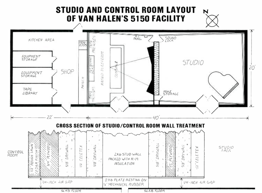
The Van Halen home, surrounded by tall trees and barbed wire, is located. in the hills above the San Fernando Valley, north of Los Angeles. At one end of their property existed a guest house with an unused room. Initially, we considered this as a possible control room site. After some investigation, however, we decided to gut the structure and build the studio from the ground up. Consequently, a 20 foot wide by 40 foot long structure with a shell ceiling height of 18 feet was constructed. Based on isolation requirements, 10 inch reinforced block construction was employed, all block cells being pumped full of concrete. A five inch thick reinforced slab also was poured.
While construction proceeded, we began the task of modifying the console and 3M 16 track. The UREI console had been in service at United Studio A in Los Angeles for many years. Although it had great sound, for our needs it required many modifications and additions. The decision was made to rewire the entire console, and incorporate the following modifications: a new 520 position patch bay; a new monitor selector panel; new stereo and cue busses utilizing Jensen 990 amplifiers; eight additional line inputs; and phantom power. (Extra parts, such as patch bays and vacuum cleaners, were deposited in the septic tank for semi-permanent storage.)
The deadline we faced required us to work at all hours of the day and night. Valerie Van Halen suggested that “Club Daiquiri’s” were to be consumed in great quantities to maintain the proper state of mind, Ken and Donn insisted on the continuous viewing of Blazing Saddles while consuming daiquiris.
After the basic shell was completed, the interior construction began. Possibly it was the daiquiris, but Ed wanted the control room to be sited on the north side of the structure. “I want to face North while playing.” That was the end of that.
The concrete slab layed between the control room and studio was cut in three places to decouple low frequency transmission between the two areas. In addition to conventional practices for studio construction, we used our intuitive judgement in room geometry and surface treatment, a factor that is sometimes over shadowed in current design philosophies. The pre-sent trend toward utilizing computer projections in predicting room performance has a major flaw: Humans use The Room, not Computers. Experience in a multitude of major facilities has enabled us to judge with a good degree of accuracy the dimensions and treatment that will best suit a particular room. There are numerous situations where the computer cannot factor the parameters that yield optimum room performance.
Interior Construction Common to Control Room and Studio
The space was divided into two areas, a control room being built 17 foot wide by 14 foot deep, with a ceiling height sloping from 12 to 10 feet. The remainder became the studio, measuring 17 foot wide by 23 foot deep sloping again from 12 to 10 feet. The slab was covered with half inch particle board and half inch parquet flooring. The interior walls are constructed from 2×4 studs on 16 inch centers, liberally blocked and insulated with R 19 fiberglass insulation. Wall plates rest on half inch mechanical rubber. Stud walls were covered with 4 inch plywood, % inch drywall, half inch Celetex, and inch drywall. All seams were staggered, each layer glued, and the drywall taped.
The roof consists of composition material on 1 1/8 inch plywood over 2×12 joista resting on the exterior walls. Roof joists were insulated and the bottom covered with % inch dry wall. Five feet below this a secondary ceiling was constructed on 2×12 joists, insulated with R 38 fiberglass insulation, attached to the exterior walls and isolated with half inch mechanical rubber. Both surfaces are covered with two layers of % inch drywall and 4 inch plywood. The five foot space between this secondary ceiling and the roof is used for air conditioning ducts, electrical runs, and a home for our Green EMT. A false 2×6 ceiling was constructed at a height ranging from 10 to 12 feet to accommodate lighting and air conditioning.
Special Construction
Two feet from the rear of the control room, yet another wall was constructed to house three, 48 inch high racks of outboard gear, with tape machine. soffits on either side. This wall was then carefully tested and found to be bullet proof (44 magnum JHP at two feet). Left to right acoustic symmetry was maintained throughout the construction of the control room.
The control room platform was built using 2×6 joists on 16 inch centers, resting on half inch mechanical rubber; the joists were packed with R 19 fiberglass insulation. The sub flooring consists of a layer of 4 inch plywood, half inch plywood, 4 inch particle board, and half inch oak parquet flooring.
The control room/studio wall is actually two isolated walls, each consisting of 2×6 studs on 12 inch centers, and insulated with R 19 insulation. The walls are heavily blocked, resting on half inch mechanical rubber with six inches of air space between. them. The sides facing the air space are covered with half inch Celetex, inch drywall, half inch plywood and inch drywall. The sides facing the rooms are covered with 4 inch ply wood, % inch drywall, half inch Celetex, and inch drywall.
Two 4×12 beams span the length of the control room studio wall in addition to picking up the bearing load of the false ceiling, the beams support the monitor cabinets. Two, 3 by 8 foot panes of glass were used in the control room window. Between them, a Piranha smoking a Camel, and a Club Daiquiri were installed. On the studio side, a 4 inch pane of glass was used with mechanical rubber stops, while on the control room side a ¾ inch pane of glass was used.
Soundlock doors used on either side of the control room to studio entrance were constructed using 1% inch solid core door, with the soundlock side. glued to 4 inch particle board, and the other side faced with 4 inch rough sawn cedar. Bottoms of all doors are equipped with Pemco automatic door bottoms. Interior doors are solid core two inch finished with rough sawn cedar; exterior doors are two solid core two inch, laminated using mechanical rubber.
The monitor cabinets were roughly set in position above the window. A string line on axis with the midrange horn was used to establish precise convergence at the mixer’s position. (This also corresponded to side to side center at the console bolster.) A 4×6 beam was sledged between monitor cabinets and ceiling joists to further couple the monitors to the room. Once the monitor angles were set, a three inch layer of pour stone cement was added under each cabinet. The pour stone’s function was two fold: to: provide for the monitor cabinets at a complex angle; and to enhance low frequency coupling of the monitors.
The Augspurger cabinets occupy 16 cubic feet, and each contain two JBL Model LE 15 low frequency drivers, toeing into each other at a 30 degree angle; angling the woofers in this manner tends to smooth out response in the 70 to 150 Hz region. JBL Model 2441 (375) midrange drivers with Model 2390 horn/lens assembly also were used, along with Model 2405 “Super tweeters.” The system incorporates a low level, 18 octave White passive crossover operating at 800 Hz. A high level, 6 dB per octave passive dB per passive R/C network crosses to the 2405 at 7 kHz. An H&H V 800 is used for low frequency amplification, while a V 500 powers the midrange and high frequency units; #10 stranded copper wire was used for all speaker runs. After various pink noise tests, no room EQ was found to be necessary. Provisions for small speakers are built in, but they have never been used.
Grounding Considerations
Our studio grounding system consists of two, eight foot copper ground rods. The installation procedure is as follows: a hole is excavated to a depth of four feet; the ground rods are driven into the hole leaving one foot exposed above ground level; 10 pounds of cop per sulfate crystals are then mixed into the excavated soil, and repacked around the ground rods. A 50 foot, #00 stranded copper wire then ties this ground plane to an isolated ground distribution bus in the electrical panel.
A #2 stranded copper wire connects the console ground bus to the isolated ground bus in the electrical panel. Our audio grounding scheme used the console patch bay as the ground reference lines running to and from auxiliary equipment and tape machines are grounded at the console, and lifted at the equipment. All out board gear receives its ground from the AC outlet; equipment which was supplied two pin was modified to three pin configuration. All patch cords are grounded at one end only.
One unique problem confronting us was KMPC, a 50,000 watt AM radio station sited just three miles from 5150. It was also a necessity that Ed be able to play in any location facing any direction, without hum, RF, or noise problems. Our solution was to build a chicken coop (grounded, of course): standard chicken wire was used in the walls, flooring, and ceiling to surround the entire recording area. The wire enclosure was tied to our central ground, and at no point touched any electrical conduits. The concept worked flawlessly.
The electrical panel is located between the control room and studio, away from tape machines and other equipment that is field sensitive. 5150 uses a 220V 100A panel with ample circuits for future expansion. We ran three #00 stranded copper wires from the main house to 5150 (a run of over 200 feet). The use of isolation trans formers was avoided because such devices add harmonic distortion to the AC line, causing power supplies to run hotter. Any isolation transformer also raises the impedance interconnect between studio and utility power, thereby increasing the possibility of RF interference. Extra care was taken in balancing the load of the 220V line.
All power outlets are “orange hospital grade” type, where the ground pin is isolated from the box. A #12 green wire runs from each outlet back to the isolated ground bus in the electrical panel. Also, separate neutrals were run for each circuit. The only contact between conduits is at the electrical panel. The lighting system consists of eight auto transformers (800-watt Luxtrols): four each for the control room and studio.
Air Conditioning and Heating
Air conditioning was accomplished by use of a modest sized, two-ton shock mounted roof unit for both heating and cooling. A custom sheet metal system utilizing 24 by 24 inch supply and 12 by 24 inch return ducts was built. To eliminate acoustical transmission between the rooms, sound traps were fabricated and installed in the supply and return ducts to the control room and studio. All supplies and returns were decoupled from the rooms using flex ducts. Ducting was insulation lined and isolated from structural contact.
Due to the high “R” value of the interior walls, and the high heat retention of the exterior walls, a 64 degree inside temperature is maintained while outdoor temperatures may vary anywhere between 29 and 110 degrees Fahrenheit. A petite air conditioning unit is all that is required to remove heat generated within the room.
By this time, we were anxious to hear something in the room. All we had was a cassette copy of “My Mother is a Space Cadet.” (Ed and Donn had just produced this record for Dweezil Zappa.) We were blown away with the sound of the room, even before the surface treatment was finished.
Finish Treatment
The control room was finished with rough sawn cedar on the front wall and both side walls. Burlap covered Tectum was placed on the walls from the console bolster to the rear of the control room. The rear wall was left with studs exposed and covered with Airflex insulation. The ceiling was filled with R 38 and covered with black burlap.
The studio finish consisted of rough sawn cedar on the control room/studio wall, exposed R 38 insulation in the ceiling, and sparse covering of the remaining walls with Sonex acoustic foam panels and Airiflex insulation. Our attitude on the finish treatment was to stop the finishing work when things sounded right. There is very little finish.
In addition, Ed and Valerie’s two car garage was commandeered to become a shop, tape library, instrument storage, and kitchen. The adjacent guest house also was taken to become the lounge.
The Acid Test
As we were comfortably sipping B-52s at 64 degrees a powerful Halen concoction made from equal parts of Kahlua, Baileys and Grand Marniers the first sessions in the studio resulted in the creation of the song “Jump” and the album 1984; all subsequent recording and mixing of this album was done at 5150.
Other 5150 projects include the production of Van Halen’s portion of the 1983 US Festival radio broadcast; Stereo Septic, a recording made when the unwanted studio hardware found a watery grave in the septic tank; the score for the CBS Movie of the Week, The Seduction of Gina, the score for the Universal motion picture The Wildlife; and the Grammy nominated recording of “Donut City” from The Wildlife soundtrack album. The success of these projects reflects the talent of all involved.
Let’s leave the last word to Ken Deane: “This is a functional studio; it isn’t designed to be in Better Homes & Gardens.”
STUDIO EQUIPMENT LIST
UREI 24/12 console
3M M56 16 track
Ampex MM 1200 24 track
Ampex ATR 800 two track
Ampex ATR 100 two track
JVC 8200U U Matic video recorder
Two Studer A 710 cassette recorders
Revox B 225 CD player
JBL/Augspurger monitor system
H&H power amplifiers
EMT 140ST plate reverb
Quantec Room Simulator
Four UREI 1176 limiters
Two Teletronix LA 2A limiters
Eight Valley People Kepex gates
Lexicon Super Prime Time
MXR delay Time
Lexicon Prime Time
Two Eventide Harmonizers
Two Lang PEQ 1 equalizers
Two Pultec MEQ 5 midrange equalizers
Two UREI 550 filters
Two Neumann U 48s, AKG C 12, four Neumann KM 84s, two Sony C 37As, two Neumann U 87s, two Sony ECM 50%, AKG 414, eight Shure SM 56s, four Sennheiser MD421s, and two Sennheiser MD441 microphones. 1912 Hamburg Steinway “B” piano (MIDI equipped)